Connecting the Keypad
1. Positioning the Keypad
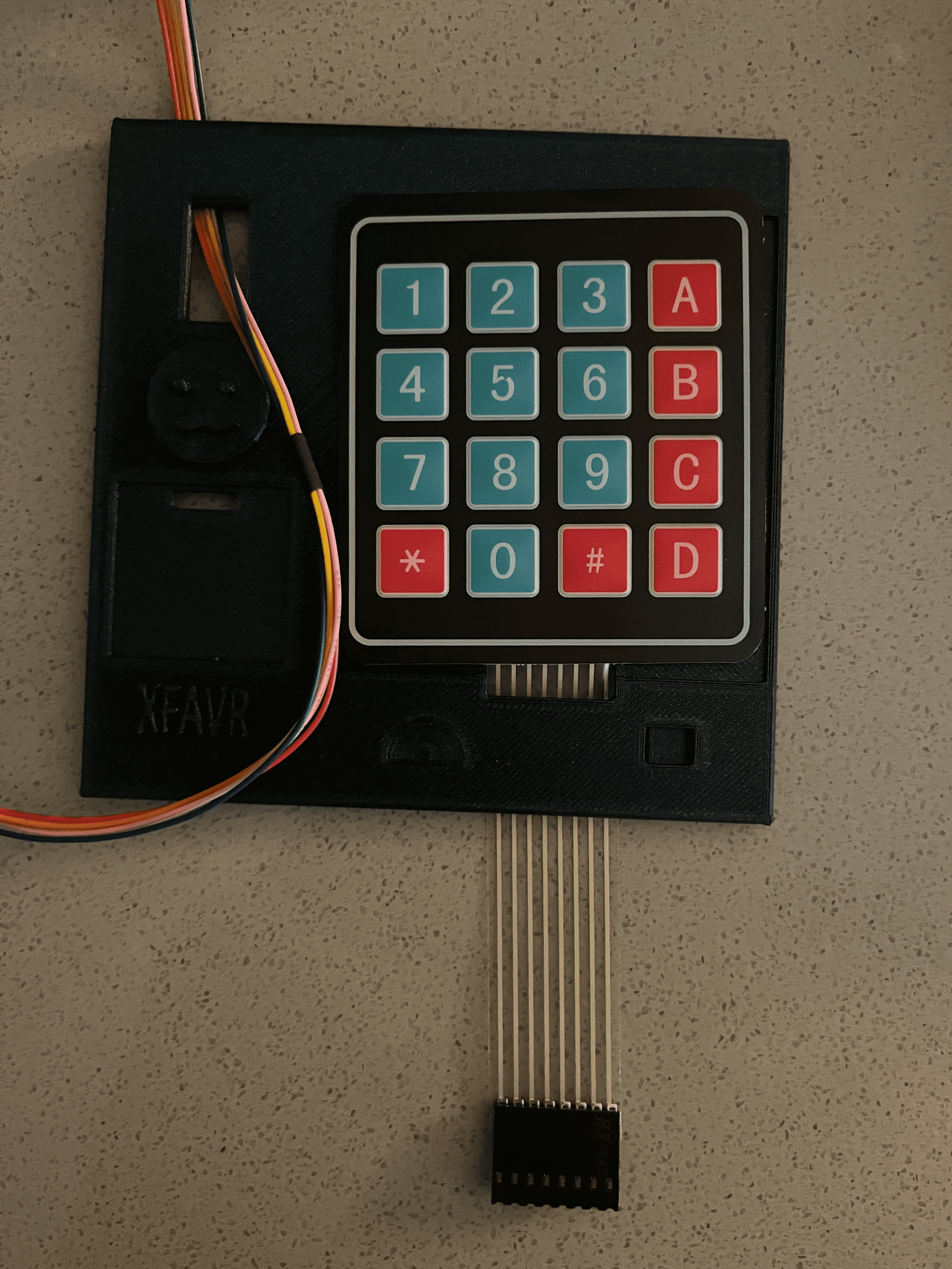
Place the keypad on the lid and feed wires through the rectangular hole directly below it:
2. Connecting the Keypad
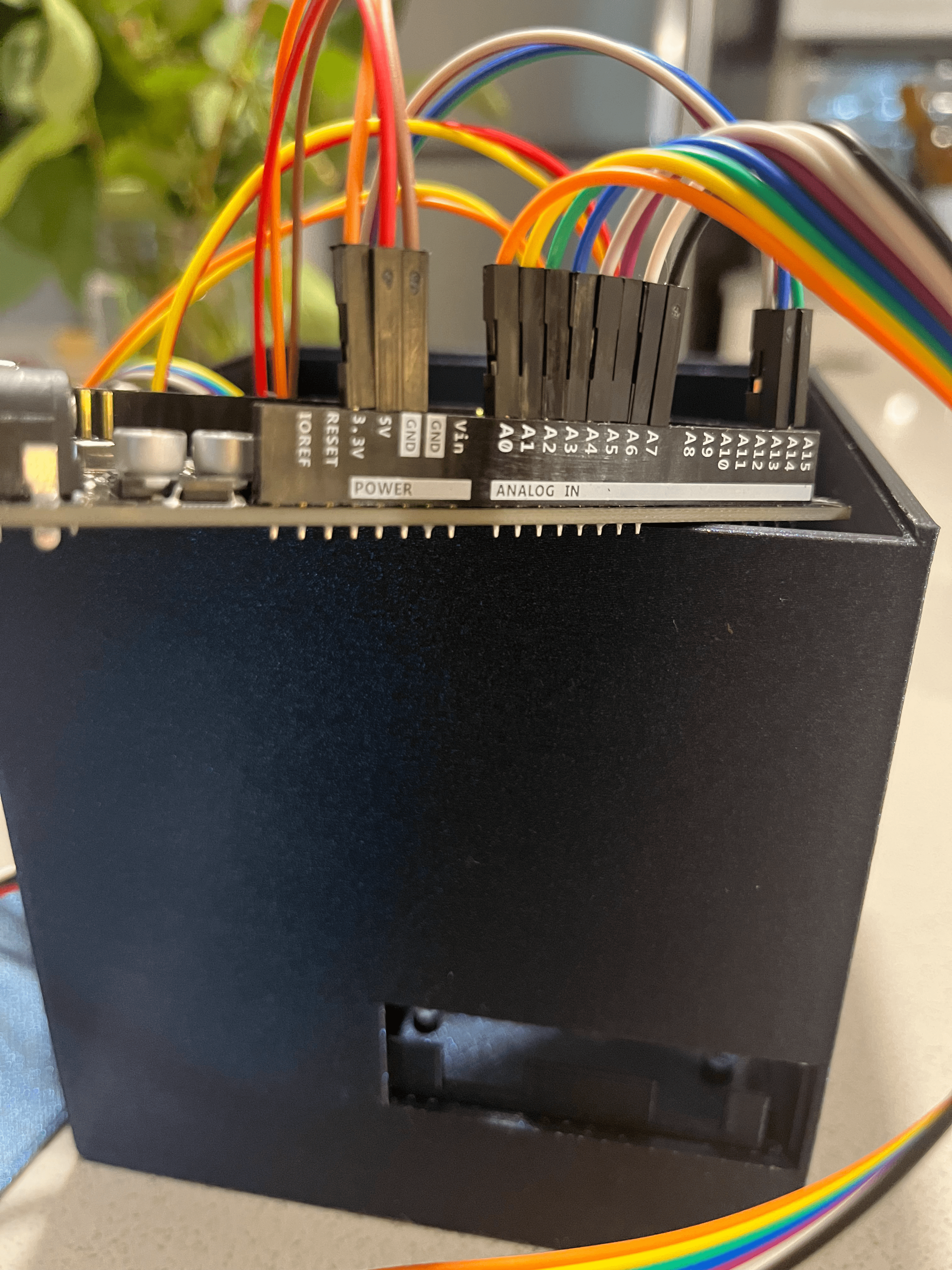
To connect the keypad input wires to the microcontroller using male-to-male jumper wires, follow the below configuration:
| From Keypad Input | To Microcontroller Pin |
|---|---|
| Right-most Input (Closest to “D” on keypad) | Pin A0 |
| 2nd Right-most | Pin A1 |
| 3rd Right-most | Pin A2 |
| 4th Right-most | Pin A3 |
| 5th Right-most | Pin A4 |
| 6th Right-most | Pin A5 |
| 7th Right-most | Pin A6 |
| 8th Right-most (1st Left-most; closest to ”*” on keypad) | Pin A7 |
A reference photo is below: