Valve Rotator
1. Connect Inputs To Microcontroller
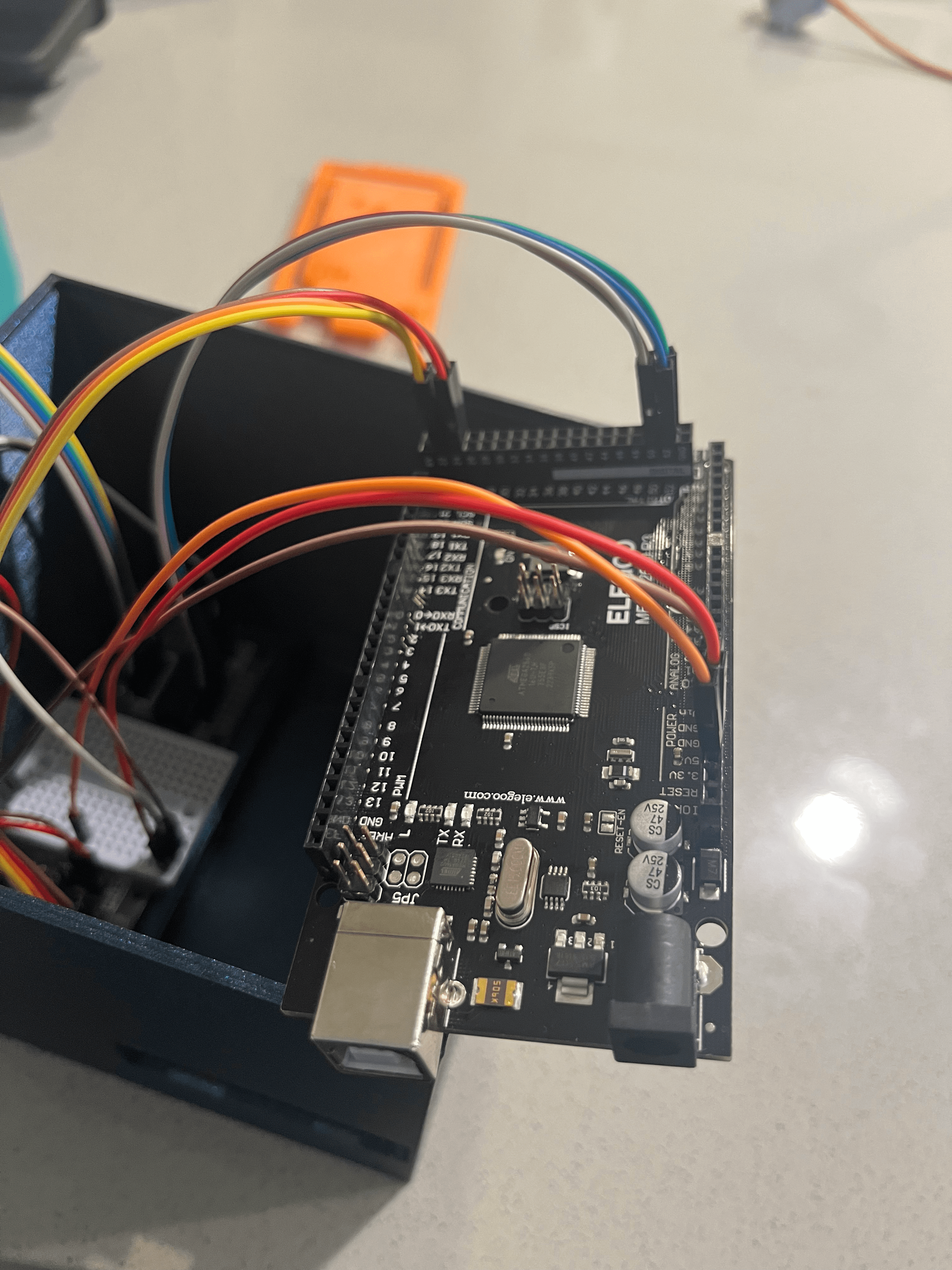
Connect the valve rotator driver inputs to the microcontroller using the following configuration:
| From Driver Input | To Microcontroller Pin |
|---|---|
| In1 | Pin 50 |
| In2 | Pin 51 |
| In3 | Pin 52 |
| In4 | Pin 53 |
An image for some help:

2. Connect Driver to Stepper Motor
-
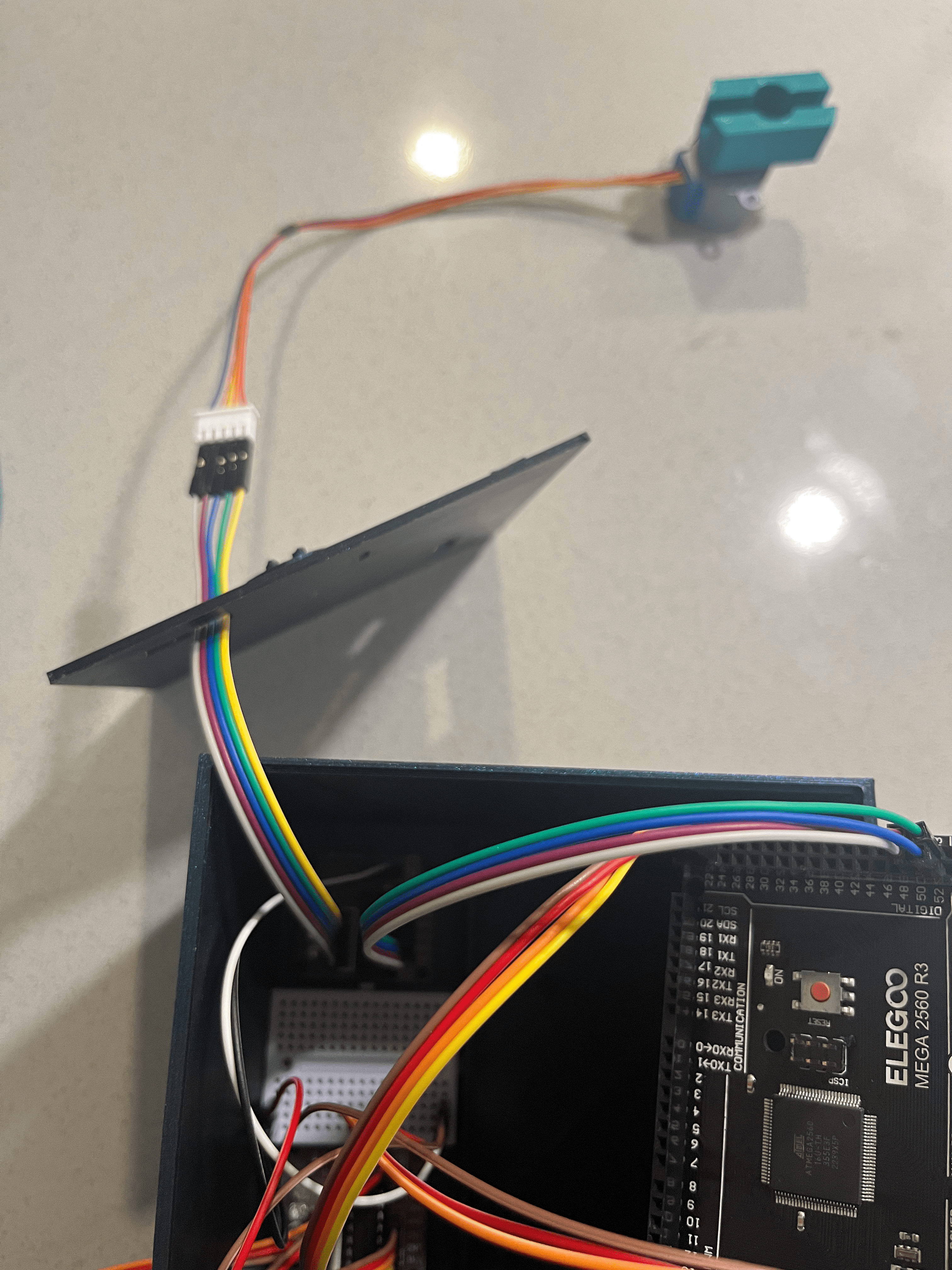
Place the stepper motor onto the valve rotator adapter component and feed the wires through the rectangular lid hole.
-
Connect the male head from the valve rotator driver wires to the female head of the valve rotator stepper motor wires. Image below for reference configuration:
